Only the most blasé of engine builders are not concerned with compression ratios. The relationship between the volume of the cylinder with the piston at the bottom of its stroke and the volume at the top of the stroke is inherently critical to engine performance. That simple comparison can help make power, improve throttle response, increase fuel mileage, and generally is one of the most important specs on any engine, either normally aspirated or super-turbocharged.
The best way to tell the compression ratio story is to start from the beginning. The factors that affect this volume relationship include the cylinder bore, piston stroke, the volume of the combustion chamber, the shape of the piston top, the position of the piston relative to the block deck (either below or above the deck), and the thickness of the head gasket.
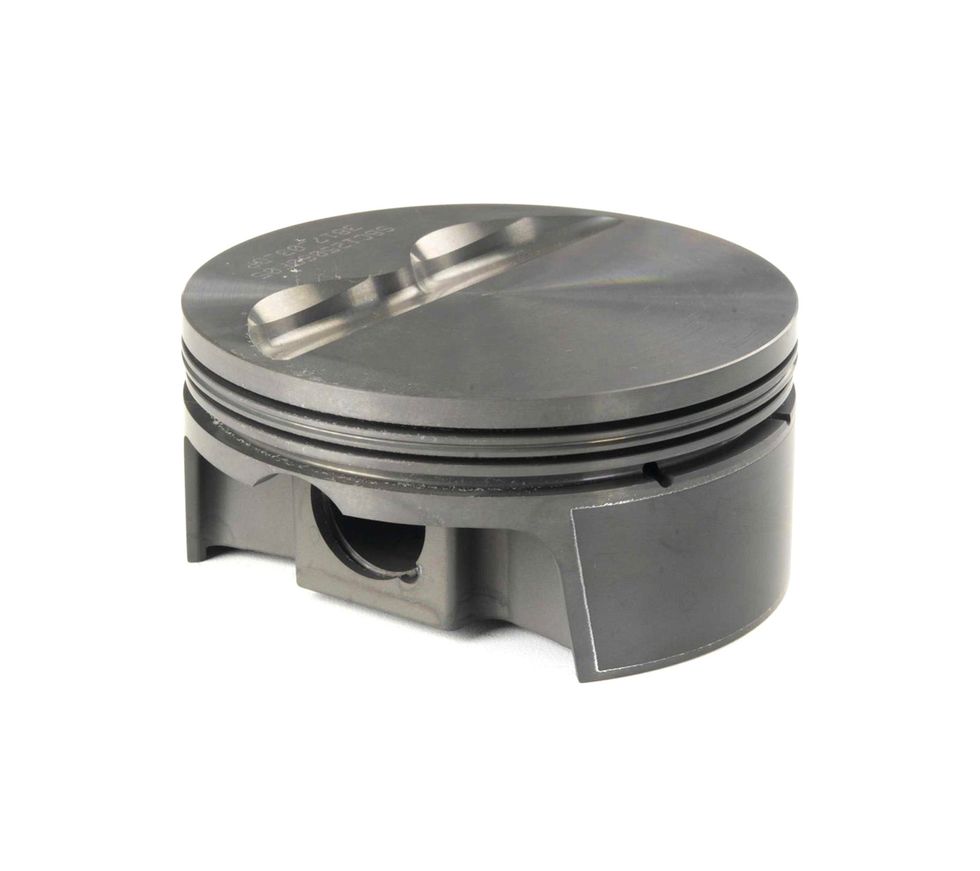
The piston top plays a vital role in determining compression on any engine. Dished pistons will add to the combustion chamber volume while domed pistons are intended to reduce overall volume and increase compression. The ideal combustion space combination is a flat piston top with a small chamber to improve combustion efficiency.Photo: Courtesy of Mahle Motorsports
Before we get into specifics, let’s first discuss how compression ratio is determined. In the old days before computers, engine builders had to run through the laborious task of determining the volume of each of the above variables. Bore and stroke for the cylinder is easy using the basic geometry of the volume of a cylinder which is the area of a circle (the bore) times the depth or length of the cylinder. The formula is from high school geometry: Pi x radius x radius x length. This is also the same formula you would use to calculate the volume of the piston above or below the deck as well as head gasket volume based on bore size and the thickness of the gasket.
The formula to compute the volume of the cylinder at the top of the stroke includes the piston top configuration (dish or dome), chamber size, head gasket thickness, and the distance the piston was either above or below the deck surface of the block. With regard to piston position, a piston that stopped its travel below the deck effectively adds this volume to the chamber size while a piston that travels above the deck would reduce that volume from the chamber.
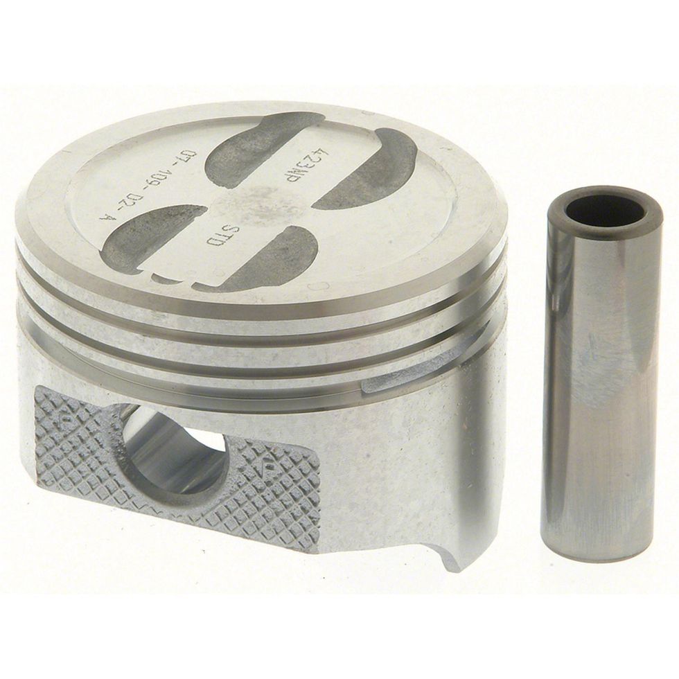
Even simple valve reliefs can affect compression. This standard four-eyebrow small-block Chevy replacement piston measures nearly 7cc’s worth of volume. Compare that to a pure flat-top, 6.0-liter Mahle piston with no reliefs. Of course, ensuring proper piston-to-valve clearance is important with either piston but the balance is always a compromise between adding compression yet avoiding bending valves when they hit the piston. Photo: Courtesy of Mahle Motorsports
We won’t get into the long-hand version of calculating compression only because it is both tedious and unnecessary now with the advent of online compression ratio computer programs. But it is important to understand the relationships between the components so that you can make decisions more effectively.
To assist in this process, you may need to convert combustion chamber volume that is usually measured in cubic centimeters (cc’s) into cubic inches or the opposite of cubic inches into cubic centimeters. We’ve listed these conversions in a separate chart to make finding them easy. As an example, a 70cc chamber converted to cubic inches would be 4.27 cubic inches.
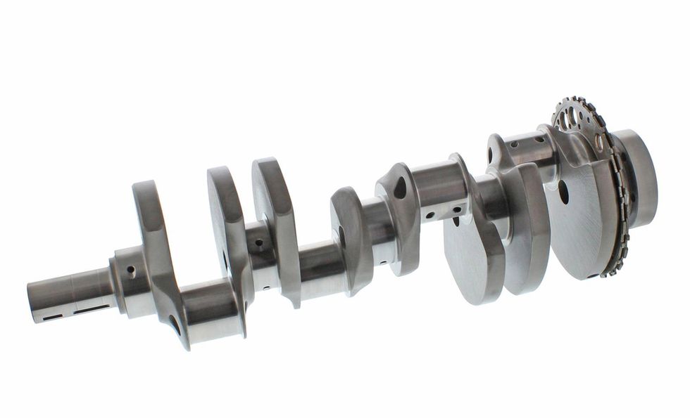
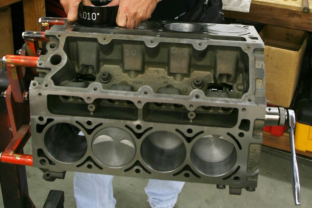
As mentioned in the story, crankshaft bore and stroke are significant contributors to compression or the lack of it. It is much easier to create compression with a longer stroke engine than one with a shorter stroke. This is a 4.00-inch stroke crank for an LS engine. Bolt this crank in with a 4.010-bore flat top piston with valve reliefs, a 70cc chamber and a near-zero deck and this will push compression up to over 10.6:1.Photo: Courtesy of Mahle Motorsports
Let’s start with the most basic item of bore size. An aspect that is not generally known is that increasing the bore size will also increase compression. As an example, let’s start with a 6.0L LS engine with a 4.00-inch bore, a 3.62-inch stroke, a 70cc combustion chamber, a pure flat top piston that is 0.005-inch below the deck surface and is using a 0.053-inch-thick head gasket.
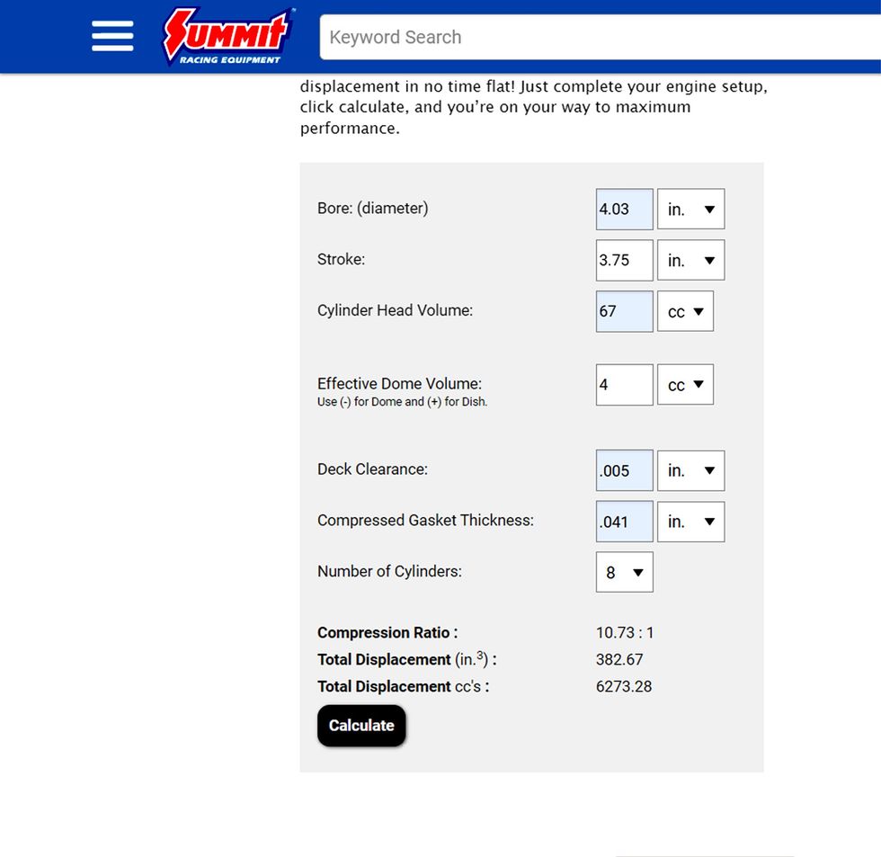
Using Summit’s free online compression ratio calculator, the program gives us a compression ratio of 10.1:1. Now, if we increase the bore diameter to 4.030-inch, this increases the static compression ratio to 10.22:1.Then, if we change to a block with a larger 4.155-inch bore, our original 10.1:1 jumps to a more impressive 10.7:1 ratio.
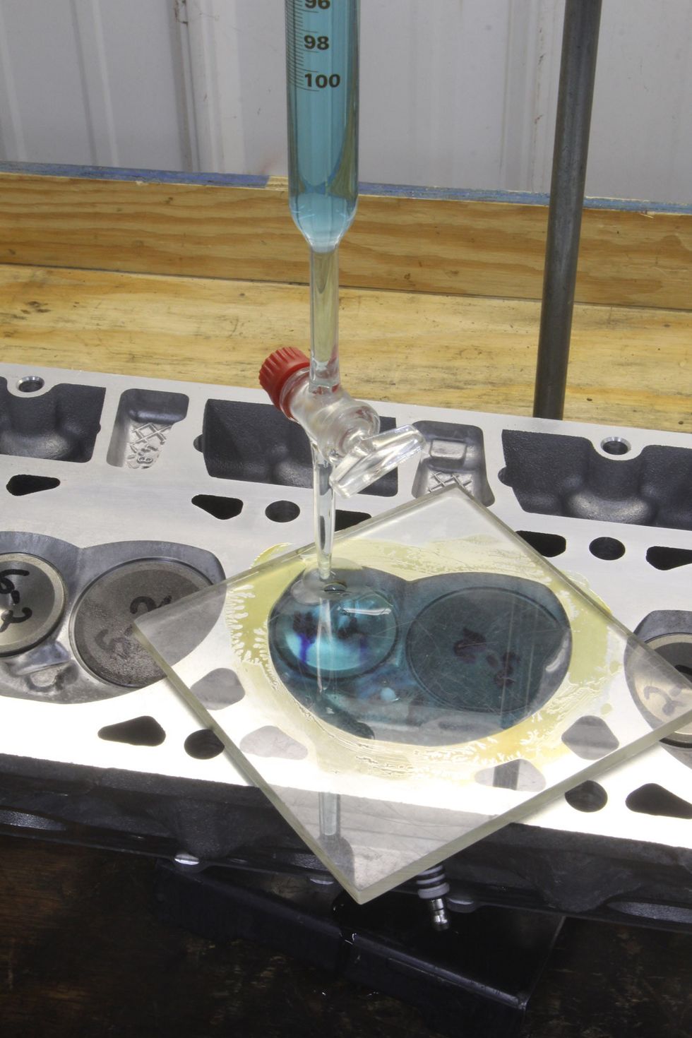
The best way to know the volume of any combustion chamber is to measure it with an affordable 100cc burette and a flat plexiglass plate. This is a simple procedure that produces very accurate results. Photo: Jeff Smith
Stroke has a much more dramatic effect on compression because of the substantial increase in volume that it creates. Let’s take our original 4.00-inch bore and 3.62-inch stroke LS engine stroke at 10.1:1 and add a 4.00-inch stroker crank to the mix. The original displacement was 364ci but now with a longer stroke, the cubic inches expand to a more impressive 402ci. On top of the displacement, this 0.380-inch increase in stroke drastically affects the compression pushing the original 10.1:1 now to 11.06:1.
The inverse is also true where a short stroke engine will have difficulty in creating static compression and is affected by small changes in chamber volume, gasket thickness, and piston top configuration. For this example, we’re going to go way back in time to a small 283ci displacement small-block Chevy to illustrate this point.
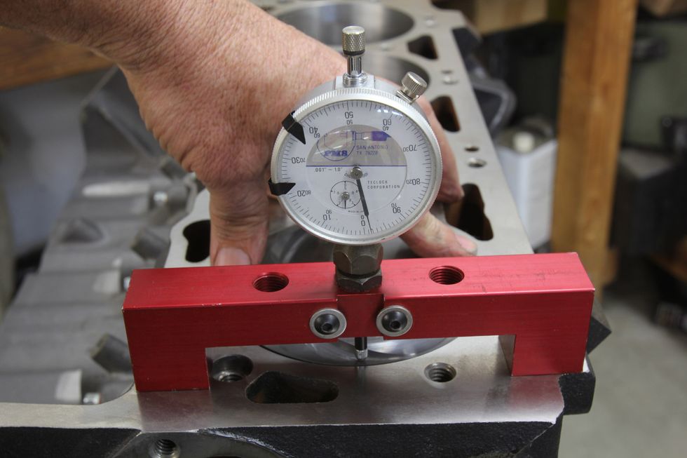
The position of the piston relative to the cylinder head deck is also critical. Most engine builders prefer to place the top of the piston at or near the deck surface, but you must also pay careful attention to piston-to-head clearance as well. A tight piston-to-head clearance for a typical wedge cylinder head engine might be 0.037-inch. Photo: Jeff Smith
The stock bore and stroke on a 283 is a combination of a 3.875-inch bore and a 3.00-inch stroke. With a 58cc combustion chamber, a flat top piston with four small (for a total of 8cc) valve reliefs, a 0.020-inch below deck height and a steel shim head gasket that is only 0.015-inch thick, the compression ratio for this engine comes out to 8.96:1. But often hot rodders will bolt a 64cc head on a 283 with bigger valves to try to make more power. What they don’t realize is that with a very short 3.00-inch stroke crank, a small chamber increase in size of 6cc has a big effect on compression. This change to a 64cc head will skewer the original compression ratio of 8.96:1 to 8.35:1 or a loss of over half a ratio!
But changes in chamber volume on a 4-inch stroke engine can be more dramatic even when the percentage of volume change is less than the smaller displacement engine. A change of 6cc in chamber volume on a 4-inch stroke, 4-inch bore engine while keeping all the other variables the same is worth a change of nearly three-quarters of a full point.
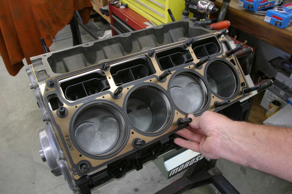
Another important variable is the compressed thickness of the head gasket. Many stock LS style MLS head gaskets can measure 0.053-inch and more. If you use one of these gaskets with a piston 0.020-inch below the deck surface, the compression ratio will suffer horribly so it’s always best to check before ordering gaskets.Photo: Jeff Smith
The numbers don’t lie. With a 4.010-inch bore, a 4.00 inch stroke, 70cc chamber, 0.051 gasket, a pure flat top piston, and a piston 0.005-inch below the deck computes out to 11.15:1, but add 6cc with a larger chamber and the compression drops to 10.45:1 or a drop of 0.70:1 in the ratio. These examples offer clues as to how easy it is to generate compression by simple changes.
Even the smallest details can offer advantages if you pay attention to their effects. As an example, piston design is a place where the smart engine builder can take advantage of his choice of piston top configurations. Most engine builders will agree that a small combustion chamber and a flat top piston with small valve reliefs are among the best ways to not only increase compression but also optimize combustion efficiency.
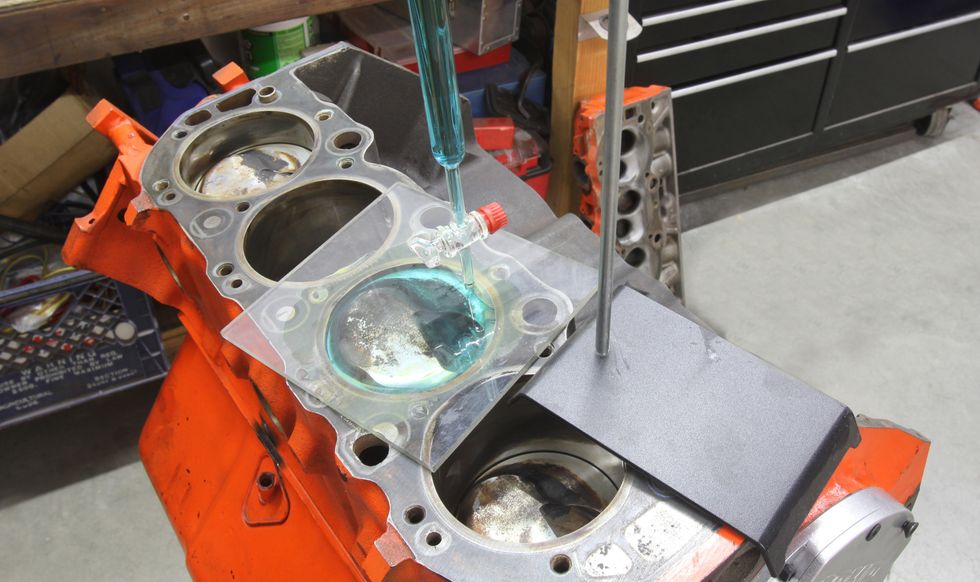
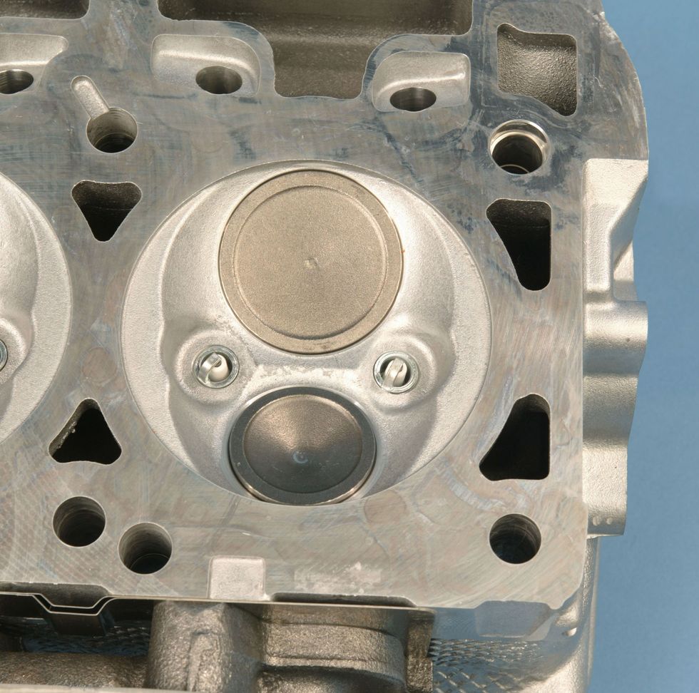
If you are working on an engine with unknown components, you can position the piston a known distance down from the deck and use a 100cc burette to measure the volume of that cylinder. Then compute the volume of a theoretical cylinder with no valve reliefs, dish, or dome. Comparing the theoretical volume with the measured one will produce an accurate description of the piston in question. In this particular case, we established an accurate measurement of the effective dome volume of this piston.Photo: Jeff Smith
The GM LS family of engines is a classic example. Even the original LQ4 6.0 liter LS truck engine from the early 2000’s offered a 7cc dished piston combined with an intermediate sized 71cc combustion chamber to create a 9.5:1 compression ratio to run on 87 octane. A simple trick to enhance power is to add a pair of 5.3L LM4/LM7 heads with smaller 61cc chambers to bump the compression and gain some near free horsepower and torque.
Our calculations reveal a 61cc chamber will push the compression a full point from 9.3:1 to 10.3:1. Even though the 5.3L heads employ smaller intake valves, the increase in compression more than compensates and overall drivability is improved with more torque and horsepower.
Besides the large component options like pistons and combustion chambers, it’s best not to overlook the smaller yet significant details like head gasket thickness and piston deck height. For most engine builders, these two measurements are linked to help establish piston-to-head clearance.
We won’t get into too many details because the options are near limitless. But generally speaking a piston-to-head clearance for a street engine should be established around 0.040-inch or slightly tighter. This is important because sufficient clearance is necessary to prevent piston rock from angling the piston and hitting the combustion chamber.
The modern Gen III hemi head is a hemispherical head in name only. Note that the chamber ends on opposite sides with flat or quench areas. These quench areas help with mixture motion as the piston nears top dead center (TDC) and improves combustion efficiency. Note that all Gen III Hemi engines use two spark plugs per cylinder to compensate for the long distance the flame front would otherwise travel to complete the combustion process. Both plugs fire at the same time and thus help improve both power and fuel mileage. A single spark plug in a Gen III Hemi would require a significantly increased ignition timing to approach the power made by using two plugs per cylinder. Photo: Jeff Smith
For wedge combustion chamber engines, this also establishes a tight quench area which is defined as the area between the flat areas of the chamber and the piston. As the piston arrives at TDC the tight clearance between the head and piston pushes (or squishes) the air and fuel into the chamber. This creates turbulence in the chamber and helps to stir the air and fuel into a more homogenous mixture that will combust more efficiently.
This means if you have an engine like an older small-block Chevy where the piston is buried deep in the cylinder to perhaps 0.025-inch, a thinner head gasket can be used to maintain the piston-to-head clearance at around 0.040-inch or less. One example of this would be the coated thin steel head gasket from Fel-Pro that measures only 0.015-inch (PN 1094) for a 350ci small-block Chevy. This will improve compression compared to a much thicker composition head gasket.
We’ve covered quite a bit of ground regarding compression ratio in hopes of offering some solutions or opportunities that you can take advantage of when building your next engine. It’s often the little details that can make all the difference.
Conversions
- To convert cubic inches to cubic centimeters, multiply by 16.3871
- To convert cubic centimeters to cubic inches, multiply by 0.0610
Scaling Back The Squeeze

Many muscle car engines from the late 1960s and early 1970s benefitted from compression ratios that were as high as 11:1. With today’s watered-down 91 and occasional 93 octane premium fuel, this often isn’t sufficient to prevent those older engines from detonating. Sure, you can mix in a little octane booster or race gas, but that’s expensive.
With today’s fuel, most sources will suggest no more than 9.0:1 for a compression ratio with iron heads. Our experience indicates you can run closer to 10:1 if the piston-to-head clearance is tight and the heads offer a decent, more modern chamber – like the newer LS engines, for example. Older engines with poor chambers tend to rattle with more than 10:1 to 10.5:1. Camshaft timing also has an effect on performance with bigger cams demanding more static compression compared to a street engine with milder cam timing. These engines are run more favorably with less compression. Of course, the more compression, the more power the engine will make with better efficiency so it’s a critical point.
It’s also possible to slow down the ignition curve and reduce timing, but these tend to make the engine run sluggish and unresponsive, which is not fun to drive. While you could rebuild the engine with a lower compression ratio with different pistons or cylinder heads, there are other alternatives.
Let’s take an example and show how we could reduce the static compression ratio on an original 350-cu.in. LT1 small-block Chevy without changing pistons or using different cylinder heads with larger combustion chambers.
We simulated a 1970 LT1 using Summit Racing’s online compression ratio program. We came up with a 4.00-inch bore, 3.48-inch stroke, a 64cc chamber and a piston with a roughly 2cc dome (it’s really bigger but once the valve reliefs are subtracted from the dome volume, the net volume change is roughly 2 cc’s), with the piston 0.025-inch below the deck running a 0.020-inch head gasket. This combination creates a compression ratio of 11.2:1. Often back in those days the compression ratio was often lower than the specs due to production tolerances, but we’ll use these numbers.
One way to reduce compression would be to add a thicker, composition style head gasket. For example, merely replacing the stock shim gasket with a Fel-Pro 0.041-inch composition version will drop the static compression ratio down from 11.2:1 to 10.58:1. This will help but there are repercussions with this approach. This move changes the piston-to-head clearance from roughly 0.045-inch to a much wider 0.066-inch. This reduces the quench effect and might create a situation where this makes the engine more detonation sensitive. This is something to consider before choosing this approach.
A more time-consuming idea would be to increase the combustion chamber volume through grinding the iron chambers. With the addition of 4 cc’s to the chamber volume with the same thin had gasket, it’s possible to cut the compression to 10.64:1. This approach will require some knowledge and skill with a grinder, but it is possible. Of course, using a 68cc aftermarket head will be much better as these more modern heads offer far better chamber designs that can enhance power while often not requiring as much ignition timing.
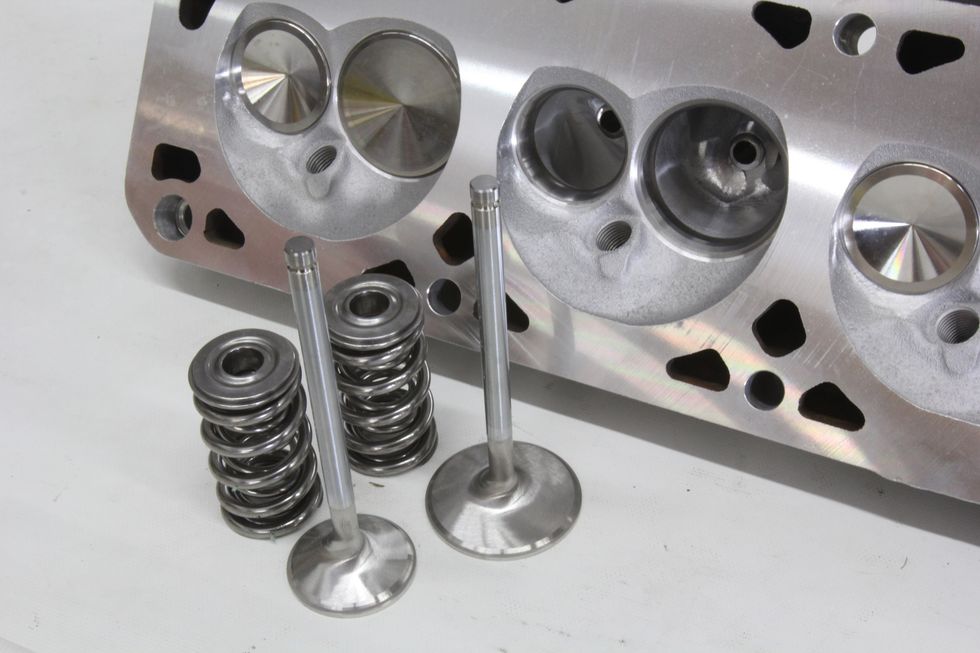
It’s also possible to add dished intake and exhaust valves that will add one or two cc’s worth of volume with a recessed valve face that might add a slight amount of volume to the chamber. This also reduces the valve weight, which is another positive approach.
These are a few of the better ideas for altering compression for earlier high compression engines. If you have a late ‘70s engine, it will have the exact opposite issue of desperately needing compression with a boost of more than one full point just to get the engine back up somewhere close to 9:1. The best bet with these engines is to just swap to smaller chamber heads. Going from a 76cc chamber to 64cc chamber will pump the compression a full point on a typical 350-cu.in. small-block Chevy.
Sources
Mahle Clevite
800-338-8786
mahle-aftermarket.com
Summit Racing
800-230-3030
summitracing.com
Commercials Cooperation Advertisements:
(1) IT Teacher IT Freelance

立刻註冊及報名電腦補習課程吧!
电子计算机 -教育 -IT 電腦班” ( IT電腦補習 ) 提供一個方便的电子计算机 教育平台, 為大家配對信息技术, 電腦 老師, IT freelance 和 programming expert. 讓大家方便地就能找到合適的電腦補習, 電腦班, 家教, 私人老師.
We are a education and information platform which you can find a IT private tutorial teacher or freelance.
Also we provide different information about information technology, Computer, programming, mobile, Android, apple, game, movie, anime, animation…
(2) ITSec

www.ITSeceu.uk
Secure Your Computers from Cyber Threats and mitigate risks with professional services to defend Hackers.
ITSec provide IT Security and Compliance Services, including IT Compliance Services, Risk Assessment, IT Audit, Security Assessment and Audit, ISO 27001 Consulting and Certification, GDPR Compliance Services, Privacy Impact Assessment (PIA), Penetration test, Ethical Hacking, Vulnerabilities scan, IT Consulting, Data Privacy Consulting, Data Protection Services, Information Security Consulting, Cyber Security Consulting, Network Security Audit, Security Awareness Training.
Contact us right away.
Email (Prefer using email to contact us):
SalesExecutive@ITSec.vip